| Items |
 /Asset/a1370.jpg /Asset/a1370.jpg HLCG High Load Capacity Grating |
 /Asset/a1073.jpg /Asset/a1073.jpg MMAF Micro-Mesh Access Flooring |
 /Asset/a1079.jpg /Asset/a1079.jpg AMG Airmesh and Multigrid Grating |
 /Asset/a1083.jpg /Asset/a1083.jpg FP Floor Plate |
 /Asset/a1086.jpg /Asset/a1086.jpg CG Covered Grating |
|||||||||||||||||||||||||||||||||||||||||||||||||||||||||
| Allowable Spans for Vehicular Loads |
N/A
Notes
|
N/A | N/A | N/A | N/A | |||||||||||||||||||||||||||||||||||||||||||||||||||||||||
| No of Bars/Foot of Width | N/A 12 | N/A | N/A | N/A | N/A | |||||||||||||||||||||||||||||||||||||||||||||||||||||||||
| Load Bar Width | N/A 0.43" | N/A | N/A | N/A | N/A | |||||||||||||||||||||||||||||||||||||||||||||||||||||||||
| Load Bar Centers | N/A 1" | N/A | N/A | N/A | N/A | |||||||||||||||||||||||||||||||||||||||||||||||||||||||||
| Open Area | N/A 48% | N/A | N/A | N/A | N/A | |||||||||||||||||||||||||||||||||||||||||||||||||||||||||
| Approximate Weight | N/A 6.2 psf | N/A | N/A | N/A | N/A | |||||||||||||||||||||||||||||||||||||||||||||||||||||||||
| Panel Size | N/A 6' x 4' (span) | N/A | N/A | N/A | N/A | |||||||||||||||||||||||||||||||||||||||||||||||||||||||||
| Engineering Properties Per Ft of Width |
N/A
A = 7.45 in² I = 1.39 in4 S = 1.80 in³ Average EI = 2,400,000 lb-in² |
N/A | N/A | N/A | N/A | |||||||||||||||||||||||||||||||||||||||||||||||||||||||||
| No of Bars/Foot of Width | N/A 12 | N/A | N/A | N/A | N/A | |||||||||||||||||||||||||||||||||||||||||||||||||||||||||
| Load Bar Width | N/A 0.48" | N/A | N/A | N/A | N/A | |||||||||||||||||||||||||||||||||||||||||||||||||||||||||
| Load Bar Centers | N/A 1" | N/A | N/A | N/A | N/A | |||||||||||||||||||||||||||||||||||||||||||||||||||||||||
| Open Area | N/A 48% | N/A | N/A | N/A | N/A | |||||||||||||||||||||||||||||||||||||||||||||||||||||||||
| Approximate Weight | N/A 8.4 psf | N/A | N/A | N/A | N/A | |||||||||||||||||||||||||||||||||||||||||||||||||||||||||
| Panel Size | N/A 6' x 4' (span) | N/A | N/A | N/A | N/A | |||||||||||||||||||||||||||||||||||||||||||||||||||||||||
| Engineering Properties Per Ft of Width |
N/A
A = 10.26 in² I = 3.40 in4 S = 3.27 in³ Average EI = 6,000,000 lb-in² |
N/A | N/A | N/A | N/A | |||||||||||||||||||||||||||||||||||||||||||||||||||||||||
| No of Bars/Foot of Width | N/A | N/A 16 | N/A | N/A | N/A | |||||||||||||||||||||||||||||||||||||||||||||||||||||||||
| Load Bar Width | N/A | N/A 1/4" | N/A | N/A | N/A | |||||||||||||||||||||||||||||||||||||||||||||||||||||||||
| Bottom Load Bar Centers | N/A | N/A 1-1/2" | N/A | N/A | N/A | |||||||||||||||||||||||||||||||||||||||||||||||||||||||||
| Top Load Bar Centers | N/A | N/A 3/4" | N/A | N/A | N/A | |||||||||||||||||||||||||||||||||||||||||||||||||||||||||
| Open Area | N/A | N/A 44.4% | N/A | N/A | N/A | |||||||||||||||||||||||||||||||||||||||||||||||||||||||||
| Approximate Weight | N/A | N/A 4.5 psf | N/A | N/A | N/A | |||||||||||||||||||||||||||||||||||||||||||||||||||||||||
| Load and Deflection Data | N/A |
N/A
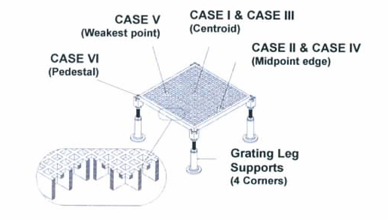
Load capacity and deflection data was developed using the Recommended Test Procedures for Access Floors by the Ceilings & Interior Systems Construction Association (CISCA). Setup requires that panels “…shall be supported on an understructure support identical to that utilized in an installed system”. All Load Points 1" Aquare 
Conditions:
|
N/A | N/A | N/A | |||||||||||||||||||||||||||||||||||||||||||||||||||||||||
| Square Mesh | N/A | N/A | N/A 1/2"-1-1/2" | N/A | N/A | |||||||||||||||||||||||||||||||||||||||||||||||||||||||||
| No of Bars/Foot of Width | N/A | N/A | N/A 8 | N/A | N/A | |||||||||||||||||||||||||||||||||||||||||||||||||||||||||
| Load Bar Width | N/A | N/A | N/A 1/8" | N/A | N/A | |||||||||||||||||||||||||||||||||||||||||||||||||||||||||
| Open Area | N/A | N/A | N/A 87% | N/A | N/A | |||||||||||||||||||||||||||||||||||||||||||||||||||||||||
| Load Bar Centers | N/A | N/A | N/A 1-1/2" | N/A | N/A | |||||||||||||||||||||||||||||||||||||||||||||||||||||||||
| Approximate Weight | N/A | N/A | N/A 0.8 psf | N/A | N/A | |||||||||||||||||||||||||||||||||||||||||||||||||||||||||
| Square Mesh | N/A | N/A | N/A 1/2"-2" | N/A | N/A | |||||||||||||||||||||||||||||||||||||||||||||||||||||||||
| No of Bars/Foot of Width | N/A | N/A | N/A 6 | N/A | N/A | |||||||||||||||||||||||||||||||||||||||||||||||||||||||||
| Load Bar Width | N/A | N/A | N/A 3/16" | N/A | N/A | |||||||||||||||||||||||||||||||||||||||||||||||||||||||||
| Open Area | N/A | N/A | N/A 82" | N/A | N/A | |||||||||||||||||||||||||||||||||||||||||||||||||||||||||
| Load Bar Centers | N/A | N/A | N/A 2" | N/A | N/A | |||||||||||||||||||||||||||||||||||||||||||||||||||||||||
| Approximate Weight | N/A | N/A | N/A 0.96 psf | N/A | N/A | |||||||||||||||||||||||||||||||||||||||||||||||||||||||||
| Standard Panel Sizes | N/A | N/A | N/A | N/A (Custom sizes available.) 3' x 10' 4' x 8' 4’ x 12' 5' x 10' | N/A | |||||||||||||||||||||||||||||||||||||||||||||||||||||||||
| Mesh Size | N/A | |||||||||||||||||||||||||||||||||||||||||||||||||||||||||||||
| Panel Depth | N/A | |||||||||||||||||||||||||||||||||||||||||||||||||||||||||||||
| Installation Details | N/A | |||||||||||||||||||||||||||||||||||||||||||||||||||||||||||||
| Cover Depths | N/A | |||||||||||||||||||||||||||||||||||||||||||||||||||||||||||||
| Standard Tickness | N/A | |||||||||||||||||||||||||||||||||||||||||||||||||||||||||||||
|
|
||||||||||||||||||||||||||||||||||||||||||||||||||||||||||||||

Sterling Process Equipment and Services, Inc.
333 McCormick Blvd., Columbus, Ohio 43213
Phone: 614.868.5151 Fax: 614.868.5152
Email: sales@sterlingpe.com